Z-stacking
Tissue presented on a glass slide can be obtained in three fashions: tissue slides by a microtome from a FFPE tissue block is typically completely flat. This means a scanner can usually obtain an optimal focus point and scan a large area of tissue in a single pass.
The two other types of samples however are typically not flat: both cytological samples and needle aspirations contain clumps of cell (a pap smear test is a good example); if samples from FFPE tissue blocks are mirror-like surfaces (at least with respect to smoothness), then cytological samples are more like the gravel surface on a tennis court.
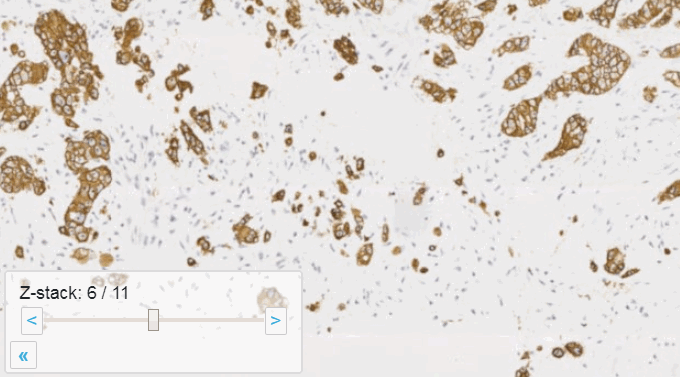
Slide scanners can’t decide on a single layer within the tissue to obtain a “one size fits all” focus, so they typically scan a number of sequential planes. This is your z-stack. Pathomation software supports z-stack data from various scanner vendors.
Beyond viewing
Allowing an end-user to navigate through a z-stack is nice, but can be very tedious and time consuming. Imagine that we have a z-stack with 4 images, then each individual layer can look like this:
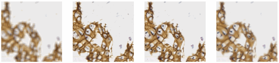
A skilled pathologist or researcher can scan through a complete slide in under 10 minutes, but it takes time to acquire this skill, and even so: much of that time is still spent zooming in and out, looking for the optimal sharpness in many regions of the slide.
Can we then use an algorithm to at least select out the most out-of-focus and in-focus tiles in a tiled z-stack? Of course the answer is yes (or we wouldn’t be writing about it)!
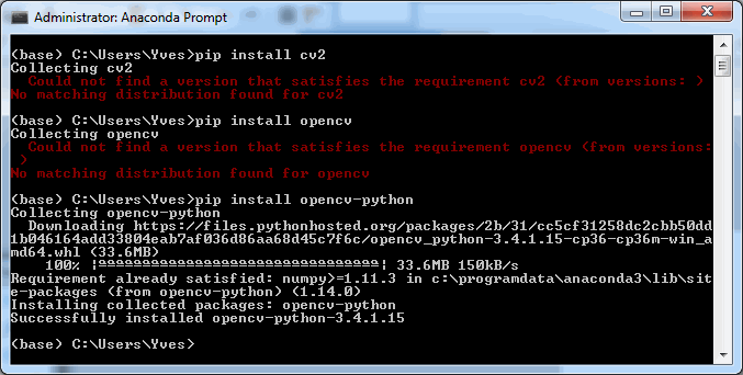
To follow along with the rest of this blog, you’ll need a Jupyter environment (we use Anaconda), a Python programming environment, as well as the PMA_python, Matplotlib, Numpy, and OpenCV packages. You can learn here about setting up PMA_python in Anaconda; take care that you install OpenCV with the correct package name, too (it’s PyPI package name is actually opencv-python, even though you import it into your code as “cv2”):
Let’s first see about reading in all images in an array (and visualize them as a sanity check):
import matplotlib.pyplot as plt
import numpy as np
import cv2

folder = "C:/Users/Yves/blog/"
image_names = ["z-stack1.jpg", "z-stack2.jpg", "z-stack3.jpg", "z-stack4.jpg"]

images = [plt.imread(folder + i_name) for i_name in image_names]

for idx in range(1, len(images)+1):
    plt.subplot(1, len(images), idx)
    plt.imshow(images[idx-1])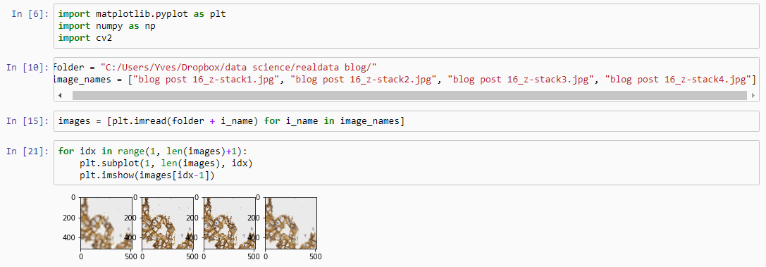
Next, let’s apply an OpenCV blurring filter on each image and compute the difference between the pixel-values in the original image and the blurred image.
blur = []
diff = []

for idx in range(0, len(images)):
    blur.append(cv2.blur(images[idx],(5,5)))
    diff.append(np.abs(blur[idx] - images[idx]))
And plot the result (although admittedly visualization of the diff-arrays doesn’t necessarily reveal much information):
for idx in range(0, len(images)):
    plt.subplot(len(images), 3, 1),plt.imshow(images[idx]),plt.title('Original tile ' + str(idx+1))
    plt.xticks([]), plt.yticks([])
    plt.subplot(len(images), 3, 2),plt.imshow(blur[idx]),plt.title('Blurred tile ' + str(idx+1))
    plt.xticks([]), plt.yticks([])
    plt.subplot(len(images), 3, 3),plt.imshow(diff[idx]),plt.title('Difference tile ' + str(idx+1))
    plt.xticks([]), plt.yticks([])
    plt.show()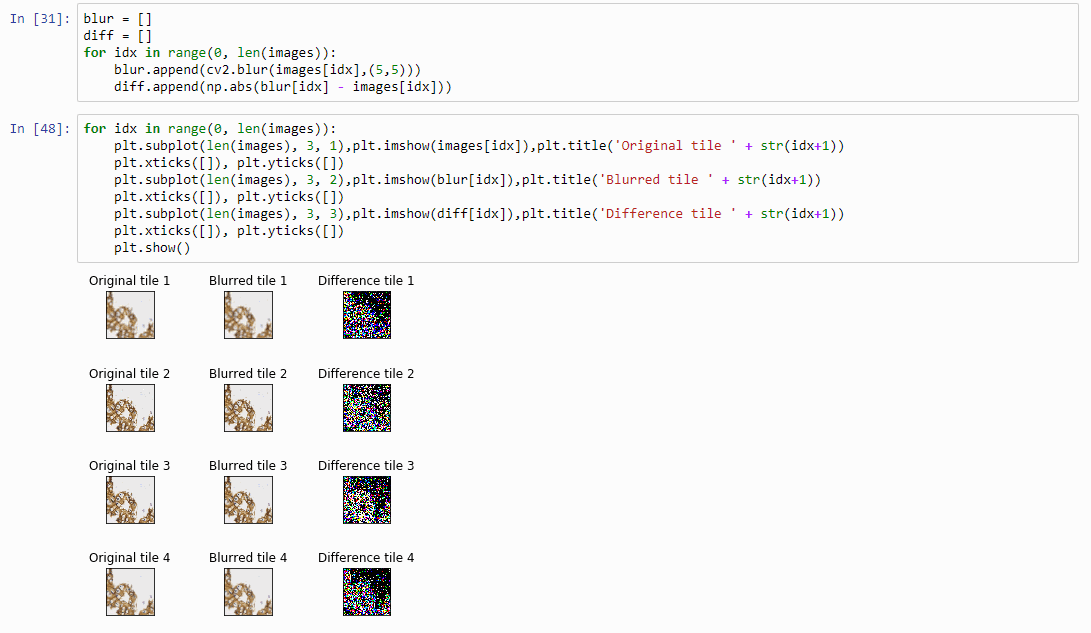
The idea behind our exercise is the following: a blurred image that is blurred, will show less difference in pixel-values, compared to a sharp images that is blurred with the same filter properties.
Therefore, we can now compute the sum of all the values in the diff-array and identify the indices of the lowest and highest values. For our z-stack, the index that contains the smallest summed differences will point to the blurriest (or “most blurred”?) image; the index that contains the largest summed difference will point to the sharpest image. Let’s see if this works:
diff_sums = [np.sum(arr) for arr in diff]

idx_blurriest = diff_values.index(np.min(diff_sums))
idx_sharpest = diff_values.index(np.max(diff_sums))

plt.subplot(121)
plt.imshow(images[idx_blurriest])
plt.title("Blurriest tile")

plt.subplot(122)
plt.imshow(images[idx_sharpest])
plt.title("Sharpest tile")
Success! We now have a way to identify the sharpest image in a z-stack, using only free and open source software.
You can download the Jupyter notebook with the code so far here.
Sharpness heatmap
For any z-stacked slide, we can now write a loop that goes over all tiles in the slide. At each location, we retrieve all the z-stacked tiles:
def get_z_stack(path, x, y):
    z_stack = []
    for i in range(0, num_z_stacks):
        # print("getting tile from", path, " at ", x, y, " (zoomlevel", sel_zl, ") / z-stack level ", i)
        z_stack.append(core.get_tile(path, x, y, zoomlevel=sel_zl, zstack=i))
    return z_stack
Now we can calculate at each location independently the sharpest tile.
def determine_sharpest_tile_idx(tiles):
    blur = []
    diff = []

    for idx in range(0, len(tiles)):
        blur.append(cv2.blur(np.array(tiles[idx]),(5,5)))
        diff.append(np.abs(blur[idx] - tiles[idx]))
        diff_sums = [np.sum(arr) for arr in diff]

    return diff_sums.index(np.max(diff_sums))
And we can invoke these method repeatedly for each location in the slide:
zoomlevels = core.get_zoomlevels_dict(slide)
sel_zl = int(round(len(zoomlevels) / 2)) + 2     # arbitrary selection
max_x, max_y = zoomlevels[sel_zl][0], zoomlevels[sel_zl][1]

sharpness_map = []
for x in range(0, max_x):
    print (".", end="")
    for y in range(0, max_y):
        sharpness_map.append(determine_sharpest_tile_idx(get_z_stack(slide, x, y)))
Say that the thumbnail of our image look as follows:
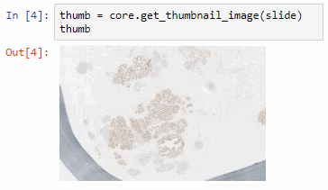
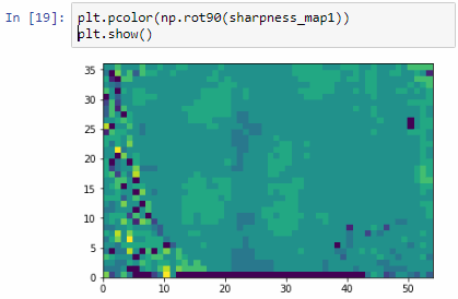
We can then print the selected optimal layers at each position as a heatmap with matplotlib.
The resulting image illustrates the fact that indeed throughout the slide, different clusters of cells are sharper in one plane or another.
The output for one of our slides looks like this:
Constructing a new single-plane image
Instead of returning the index of the sharpest tile in a stack of tiles, we can return the sharpest tiles itself. For this, we only need to make a small modification in our earlier determine_sharpest_tile_idx function.
def determine_sharpest_tile(tiles):
    blur = []
    diff = []

    for idx in range(0, len(tiles)):
        blur.append(cv2.blur(np.array(tiles[idx]),(5,5)))
        diff.append(np.abs(blur[idx] - tiles[idx]))
        diff_sums = [np.sum(arr) for arr in diff]

    return tiles[diff_sums.index(np.max(diff_sums))]
We can subsequently paste all of the sharpest tiles into a new PIL image object that is made up of the dimensions of the selected zoomlevel from which the tiles are selected:
def get_focused_slide(slide, zoomlevel):
    x_count, y_count, n = core.get_number_of_tiles(slide, zoomlevel)
    x_tile_size, y_tile_size = core.get_tile_size()
    focused_tiles = []

    image = Image.new('RGB', (x_count * x_tile_size, y_count * y_tile_size))

    coords = list(map(lambda x: (x[0], x[1], zoomlevel), itertools.product(range(y_count), range(x_count))))

    for x in range(0, max_x):
        print (".", end="")
        for y in range(0, max_y):
            focused_tiles.append(determine_sharpest_tile_idx(get_z_stack(slide, x, y)))

    i=0
    for y in range(y_count):
        for x in range(x_count):
            tile = focused_tiles[i]
            i+=1
            image.paste(tile, (x*x_tile_size, y*y_tile_size))

    return image
If you’ve run the code so far, you’ve already found out (the hard way) that it can actually take quite some time to loop over all tiles in the slide this way.
Therefore, let’s introduce some parallellization logic here as well:
def get_focused_tile(c):
    return determine_sharpest_tile(get_z_stack(slide, c[1], c[0], c[2]))

def get_focused_slide(slide, zoomlevel):
    x_count, y_count, n = core.get_number_of_tiles(slide, zoomlevel)
    x_tile_size, y_tile_size = core.get_tile_size()
    focused_tiles = []

    image = Image.new('RGB', (x_count * x_tile_size, y_count * y_tile_size))

    coords = list(map(lambda x: (x[0], x[1], zoomlevel), itertools.product(range(y_count), range(x_count))))

    tiles = Parallel(n_jobs=-1, verbose=2, backend="threading")(
        map(delayed(get_focused_tile), tqdm(coords)))

    i=0
    for y in range(y_count):
        for x in range(x_count):
            tile = tiles[i]
            i+=1
            image.paste(tile, (x*x_tile_size, y*y_tile_size))

    return image
Once you have the new image, saving the image to TIFF output is trivial:
image = get_focused_slide(slide, 6)    # do this at zoomlevel 6, can take a while...
image.save('focused_image.tiff')
Which in practice can end up looking like this (including parallellization progression bars):
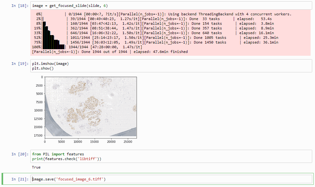
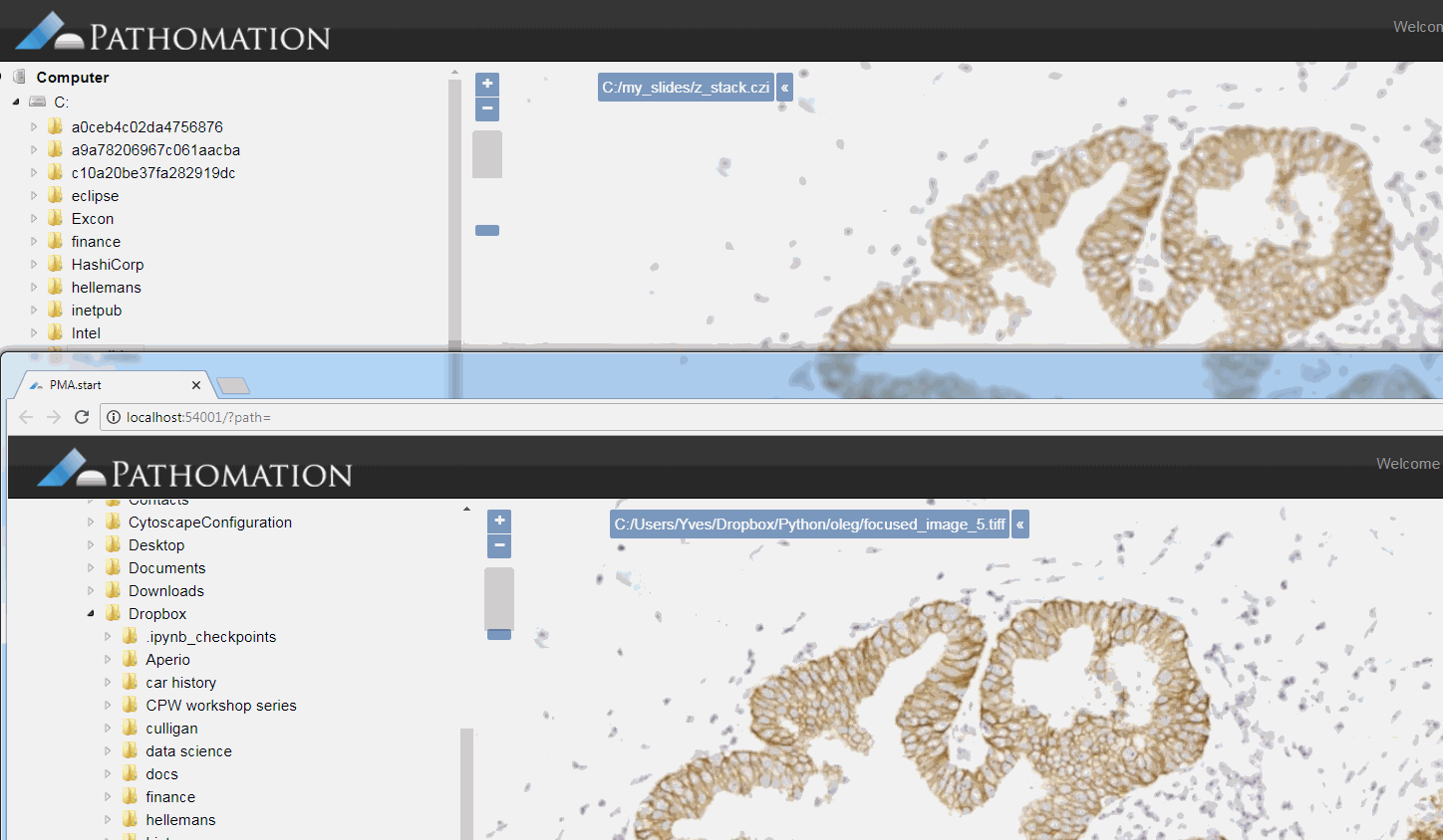
The resulting image can now be opened in turn (in PMA.start, of course) to navigate without the need to continuously having to scan for the sharpest plane.
Here’s comparison of a random zoomlevel in the original image with the same region of interest in the new optimized image:
The sourcecode for this procedure so far can be downloaded as another Jupyter notebook (thanks Oleg Kulaev for helping with the finer details of parallellization and image orientation handling in matplotlib).
Cool huh? Well, sort of, kinda… read on.
Libvips to save our TIFFs
There’s an implicit problem with the TIFFs that we generate: they’re big! Most importantly… they’re flat.
There’s some irony to this. We spent all this effort flattening the z-stacked CZI file for a flat TIFF, which is infinitely slower to navigate than the original CZI!
So saving as a pyramidal TIFF instead of a flat tiff would definitely help our case here.
The quickest way to do this is through libvips, with pyvips bindings installed (make sure that you install libvips before getting pyvips with pip; also, if you’re on Windows, make sure that the libvips’ \bin folder is included in your SYSTEM path variable).
Our final step therefore is getting our “flat” PIL image object to a pyramidal tiff (if you need to freshen up about why the pyramid exists in these files, see our section on Whole Slide Images and pyramid stacks in https://realdata.pathomation.com/digital-microscopy-imaging-data-with-python/)
import pyvips

dtype_to_format = {
 'uint8': 'uchar',
 'int8': 'char',
 'uint16': 'ushort',
 'int16': 'short',
 'uint32': 'uint',
 'int32': 'int',
 'float32': 'float',
 'float64': 'double',
 'complex64': 'complex',
 'complex128': 'dpcomplex',
}

img_3d_array = np.asarray(image)
height, width, bands = img_3d_array.shape
linear = img_3d_array.reshape(width * height * bands)
pyvips_image = pyvips.Image.new_from_memory(linear, width, height, bands, dtype_to_format[str(img_3d_array.dtype)])

tile_width, tile_height = core.get_tile_size()
pyvips_image.write_to_file('pyramidal_image.tiff', tile=True, tile_width=tile_width, tile_height=tile_height, pyramid=True)
This final procedure is available as yet another separate Jupyter notebook. Once again much gratitude goes to Oleg Kulaev for figuring out the libvips interactions.
Curious about how to identify blurry tiles in single plane brightfield images? We have a post about that, too.
Optimization
The procedure as described can still take quite a while to process. The time needed is highly dependent on the selected zoomlevel. Deeper zoomlevels give you better accuracy, but at the expense of having to process more pixels.
We wrote this post mostly to explain the principle of how blur detection and z-stack optimization can work. By no means do we claim that is production-ready code. If you need professional, scalable blur-detection methods, check out e.g. David Ameisen‘s start-up company ImginIT (just don’t expect his process to be as clearly explained as we just did).
Here are a couple of ideas for optimization:
- Do we really need to consider all pixels in a tile? Can we get by with selecting perhaps every other 2nd, 4th, 8th… pixel perhaps?
- Do we need to run the blur detection on tiles from zoomlevel x in order to determine the right layer to select from? Perhaps we can get by with zoomlevel x – 1, x – 2…
- Do we need to process tiles in their entirety? Perhaps we can select tiles from a coarser zoomlevel, artificially break up an individual tiles in smaller tiles, and use those as a reference.
- Last but not least, do we even need all contingent tiles? This is easiest to illustrate in a 1-dimensional world: if the optimal layer to select from for tile 1 and tile 3 are the same, is there still any point to examine tile 2 as well? It’s easy now to conceive a recursive algorithm that starts with a (possibly even random) selection of tiles that only analyzes intermediate tiles as the need arises.
In a next post we’ll be discussing how you can use PMA.start to generate DICOM-compliant image objects.